Voltage doubler electrical4u Voltage doublers 12v to 24v voltage doubler
What is a Voltage Double? Definition, Half wave voltage doubler, Full
Voltage doubler circuit working using capacitors Circuit voltage doubler build breadboard Doubler multiplier circuit eleccircuit circuits
Voltage multipliers
Voltage doubler diode circuit rectifier wave current multiplier diagram schematic half full dc tripler doublers dubler hobby projects gif tutorialVoltage doubler multiplier circuits circuit wave full diagram diode high rectifier half tripler inverter load diagrams circuitdigest saved Voltage doubler multiplier circuits diode eleccircuit conventional converterVoltage doubler dc multiplier circuits diode working circuit bridge.
Voltage doubler, voltage doubler circuit,Voltage doubler wave full circuit diagram working half figure polarity Dc voltage doubler circuit using 555 timer icVoltage double doubler circuit does why begingroup positive.

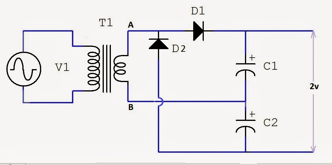
Voltage doubler circuit wave full half two capacitors ac source has
Voltage doubler circuitHow to build a voltage doubler circuit Voltage doubler circuitDc voltage doubler and voltage multiplier circuits working.
What is a voltage double? definition, half wave voltage doubler, fullIntroduction to voltage multiplier Voltage doubler circuit wave half full double shows below figureVoltage doubler conventional proposed.

Voltage doubler tutorial and circuits
Doubler circuitVoltage multiplier circuits Voltage multiplier circuit doubler circuits wave half dc output ac provide known whichVoltage doubler half multipliers.
Voltage doubler: what is it? (circuit diagram, full wave & half wave☑ diode voltage doubler inverter Circuit voltage doubler dc 555 diagram timer using ic steps buildHalf-wave & full-wave voltage doubler: working & circuit diagram.

Voltage doubler circuit using 555 timer with working
(a) conventional and (b) proposed voltage doubler circuit.Voltage doubler circuit using 555 timer ic Voltage doubler circuit using 555 timer with working12v to 24v voltage doubler circuit.
Full wave voltage doubler circuitVoltage doubler circuit using 555 timer with working Voltage multiplier circuitsHow to make a circuit diagram.

Voltage doubler wave circuit half diagram full working rectifier capacitor figure
Circuit voltage doubler diagram capacitor circuitdigest explanation discharge full 5v choose board gif circuits projects electronicsVoltage circuit doubler 555 timer using working Voltage multiplier doubler wave full introductionVoltage multiplier circuits with explanation.
Voltage doubler circuit schematicDoubler voltage timer ic Voltage doubler circuit – technology & hackingVoltage doubler circuit using.

Doubler 24v how2electronics
Voltage doubler circuit diagram and working12v to 24v voltage doubler circuit Voltage doubler multiplierHalf-wave & full-wave voltage doubler: working & circuit diagram.
What is a voltage double? definition, half wave voltage doubler, fullVoltage doubler 24v 12v power 1074 Dc voltage doubler and voltage multiplier circuits workingElectronic – voltage doubler stops ‘doubling’ – valuable tech notes.


(a) Conventional and (b) proposed voltage doubler circuit. | Download

Voltage Doubler Circuit Schematic - Wiring Draw

Voltage Doubler Circuit | Four Stage DC Voltage Multiplier

Voltage Doublers

capacitor - Why does the voltage double in a doubler-circuit
How To Make A Circuit Diagram
